2007-10-23

3ds Max 2008 released: Some Known Issues

Or "Why do my brand new 3ds Max 2008 render black when I choose a mental ray render preset"?


3ds Max 2008 has been released, and as always, some things sneak in the wasn't really intended in the final version.

Here, a "minor edit" to the rendering presets became less minor than was intended;

Since 3ds Max 2008 contains the new mr Photographic Exposure control, the rendering presets (y'know, the ones down at the bottom of the render dialog) for daylight was supposed to be changed from the old Log exposure to the new Photographic exposure set for "sunny day" lighting.

The problem? That this was done.... but by accident all mental ray render presets got this setting.

Yes, even the "plain old" settings got, by mistake, a setting suitable for a superbright sunny day enabled:


The setting accidentally put in


But a sunny day can easily be lit by 100000 lux. And your average interior surely is not. So out of the box, starting up max and putting in some photometric lights (try to use the photometric lights as often as possible, btw) you would get a really dark scene.

And even worse, putting in some non-photometric scene would yield a pretty much completely BLACK scene. Why?

Well, the new mr Photographic Exposure Control has a 2nd feature; The feature of treating any "oldschool" value as real, physical cd/m^2 values (if you wonder about what a "candela per square meter" is, go back to the "Gnomes and Basketballs" post).


The Units Setting


This means that if an "oldschool" light of the arbitrary intensity value "1.0" shines perpendicular to a white (100% reflective) lambertian surface (i.e. plain old white diffuse thingamabob), this will emit light that is interpreted as 1 cd/m^2.

Now that is really really really really REALLY really dark.

I.e. turning on max, loading a mental ray render preset, and putting in and oldschool "Omni" light gives you a black render. Not good.

The fix? Easy.

Do one of three things:

Either:

1: Turn it off altogether

Hit "8" to bring up the "Environment/Effects" dialog and do as follows:


Exposure Control Turned Off


By simply turning off the exposure control, you are back to a "known" behavior. However the exposure control is really neat and gives very nice images... so I don't really recommend that method!


2: Use the exposure controls "non physical" mode


Exposure Control in "Non Physical" mode


This is better; it still gives you all the nice image control of crushing blacks, taming highlights, camera vignetting and saturation controls, but it uses a fixed unity gain, i.e. the intensity of the pixels does not change (except it applies a gamma correction if the 3ds Max gamma is disabled, if the 3ds Max gamma is enabled, that gamma is used).

However, it is not perfect just because of the fact that you lack any control over exposure; the "non physical mode" is locked to unity gain with no control over it.

There is, however, a third variant:

3: Use the exposure control with an EV=0.0


Exposure Control with an EV of 0.0


It so happens that when using the "oldschool pixels equal cd/m^2 mode" (pictured above) the EV value of zero (0.0) is very close to the "unity gain" mode set by the "Non Physical" mode. But you can change it up or down to re-expose the scene.

So for a scene lit completely with "oldschool" lights (non photometric), that is the easiest setting with the greatest control.


A further note on the units / physical scale


Now if you have an old scene with a blend of photometric and non-photometric lights, you may want to revert to the old behavior of using the "physical scale" setting, which exists in the old Logarithmic exposure control.


Using a "Physical Scale" like in the past


In this mode you cannot use the "EV=0" setting, you probably need to pick one of the "indoor" presets, or just play with the EV until you get a "nice" image, because this means that now an oldschool light of intensity "1.0" will equate to an illuminance of ~1500 lux when perpendicular to a surface, so an exposure "suitable" for that amount of light must be used.


Hope this helps!


/Z

2007-10-14

Yer in a "Heap" of trouble now: Avoiding random crashes in Maya/Max due to running out of Windows resources!


Note; This tip has nothing to do with mental ray at all, but since the issue I describe tend to manifest on Maya when opening the mental ray control panel (due to the sheer number of tiny windows w. subwindows) I mention it here.


Have you ever run, for example, Maya (on Windows XP or earlier - Vista works better here) with a ton of other programs running, and tried to open a particularily complex AE template for some shader, to find the application go "plop" and disappear?

While there are any number of probable causes, I was debugging a particular case and actually found the cause, and it was sometihng I never really suspected, and is pretty non-obvious. And doesn't have anything whatsoever to do with mental ray, as I said above.

So what's up?


Back in the day of 16 bit Windows 3.0, running out of "window handles" (each window on screen has a "handle", like an identifier, used by the operating system to keep track of it) was extremely common, and every Windows user recognized the symptoms... windows wouldn't open, or buttons/texts would be missing from dialogs, or windows opened as only borders, or a strange "placeholder text version" of dialogs popped up.... whatever.

You'd think that a "modern" operating system wouldn't have a limit on the number of windows it could have opened, right? With multipled gigabytes of RAM, this shouldn't be an issue... right?

Well... think again. ;)

First of all the number of possible handles is apparently - still - limited to a 16 bit number (that's 65536 possible handles). But the real limit doesn't lie there, coz that's plenty. The real limit lies in the fact that each "window handle" also implies a memory allocation of a special data structure, that lives in a special memory area called the "desktop heap". And this memory area is small. As a matter of fact, by default, on XP (32 AND 64 bits) ... it's 3 megabytes!!!! Thankfully, on Vista it's larger, so Vista users do not need to do anything (except cry over all the other issues with Vista.... but that's for another blog day...)

Practically, this means that at around a few thousand windows (or other handles), things start failing.

Now, the user interface in Max, Maya and XSI are "windowed" UI's. This means that each control in each dialog is considered a "window" (from the point of view of the operating system). And sub-dialogs, little rollouts, etc. are all subwindows, with controls sub-sub-windows, and buttons can be sub-sub-sub-sub-windows, etc.

Anyone who has seen a compelex Max dialog box or Maya UI, and consider that counting every single little box, control, and thing, you'll find that that's a lot of windows. Maya easily consumes a couple of thousand handles all on it's own. (You can see this by telling your task managers "processes" tab to display the "GDI OBJECTS" column)

(Incidentally, this issue is known by Microsoft, to the extent that they try to write their software "windowless", i.e. when you run, say, Internet Exploder, each little thing on the webpage is not a separate window from the OS's point of view, precicely because of this problem!)

All is lost! The Sky Is Falling! Or?


Not at all.

See, the cool thing is that you can set up the size of the "desktop heap" by fiddling with the registry.

However, there are two things to consider when doing this, one fairly benign, and one less so.

The benign issue is that the "desktop heap" actually comes out of a larger memory area called the "Session View" (don't you just love these names?). And the size of the "Session View" is also limited (to 48Mb by default). Which is again adjustable, but that in turn lives in Kernel address space, which also is limited... to another, larger, value. And so on. You get the idea.

So the point is, you can increase the "desktop heap" size by editing the registry, but you can't just do it willy nilly and put in any old value, because you will get other problems, of running out of "Session View" space.

What I did was to up it from 3Mb to 4Mb, and the problems I had pretty much went away immediately.

The second, less benign issue, is that this is a really hairy registry location, and a horribly convoluted registry key, which actually contains a long string of some 200 characters where you have to change one thing in the middle, and the problem is the fact that doint it wrong can turn your PC into a brick.

Let me repeat that: Doing the registry edit INCORRECTLY CAN TURN YOUR PC INTO A BRICK. A DOORSTOP. A BOAT ANCHOR. MKAY!!??

So proceed with caution!

So what do I do?


Well, first of all, be aware of the above. I will take no responsibility for you turning your machine to scrap metal by a clumsy registry edit. Really. Proceed at your own risk, your own peril, and totally on your own responsibility. If you work at a studio, and the machine is not your own, talk to the TD or machine responsible person, point him to this webpage, and let him do it.

Okay?

Made that clear?

If things blow up, do not come crying to me. I warned you. Ok? Good.


The registry key in question is (and if you don't know how to edit the registry, you probably shouldn't be trying this...):


HKEY_LOCAL_MACHINE\System\CurrentControlSet\Control\Session Manager\SubSystems\Windows


The default value of this key is something like this


%SystemRoot%\system32\csrss.exe ObjectDirectory=\Windows
SharedSection=1024,3072,512 Windows=On SubSystemType=Windows
ServerDll=basesrv,1 ServerDll=winsrv:UserServerDllInitialization,3
ServerDll=winsrv:ConServerDllInitialization,2 ProfileControl=Off
MaxRequestThreads=16


...except it's all in one gargantuan long line, requiring you to scroll horizontally. See that "SharedSection" thing in there? After it it says "1024,3072,512"? Well, the 3072 in the middle, that's the "3 megabytes" we are talking about. 4 megabytes is 4 * 1024, i.e. 4096. So what we want to do is change "3072" to "4096".

Having done that, and rebooted, you should be gold.

More information about the desktop heap can be found here, or using, well, Google.

/Z

2007-10-12

Maya: No Alpha channel on mia_material(_x)?

This must rank as the "most frequently asked question ever". (And consequently, the worst use of Google ever, apparently, since CGTalk alone has more threads on the topic than you can shake a stick at).

The problem: You render stuff in Maya, using mia_material(_x) - or any other "mental ray" shader - but you find that those pixels containing that shader has no alpha. What gives?

The reality is that Maya has a very peculiar notion of Alpha... because the Maya software renderer actually has true three-colored "transparency", so transparency gets passed around separately in the most... odd... ways ;)

Hence, to get the Maya system to "understand" a standard shader that uses alpha, you need to check this here little checkbox:


Then, life should be more fun again!

/Z

2007-10-09

Hot Fuzz: Hair Revisited

In a previous post I briefly mentioned hair. People started to wonder about the details of that, so:

If you render hair w. Raytrace shadows and using the normal raytracer, it works.. but takes a while:


Whereas if one enables the Fast Rasterizer, and use Detail Shadow Maps, it can be both nicer looking and faster:


So the question then is... where do I turn this on?

I admit some things can be hard to find, and sometimes they are renamed in the UI of a particular application... for example, the mental ray detail shadow maps are actually not named "detail shadow maps" in 3DS max, they are named "Transparent Shadows". You find them here:


In Maya, however, they have their proper name and are found here:


However, Maya has "special" shadow settings for Hair and Fur one may need to watch out for.

Turning on the "Fast Rasterizer" is easier since it has it's proper name in most applications. Max:


And Maya:


Hope this helps with the "Fuzzy sidekick" rendering. Note that the Rasterizer is great for motion blur and fuzzy stuff, but can be suboptimal when involving many raytraced effects (glossy reflections, etc.)

/Z

2007-10-01

Maya's default shadow settings

Clickeroo

No too long ago I wrote about Maya and shadows.

There is another "issue" related to Maya and shadows; the default shadow trace depth on Maya is 1 (called "Ray Depth Limit" in the lights "Raytrace Shadows" panel). This means that even after one bounce (like a reflection in a mirror, or behind a pane of glass) you suddenly do not have shadows any more! This can hugely impact any quality interior GI render, and you can get all sorts of issues caused by this.

NOTE: A common misconception is that the Maya "Ray Depth Limit" on the ray traced shadows is how many surfaces the shadow rays penetrate. This is not so!.

This image is rendered with the "Ray Depth Limit" of 1:


Notice how the light still gladly penetrates 3 blue glass blocks (6 surfaces in total) and still generates a shadow? Yet when viewed through the single red glass block, the view as seen trough it suddenly is completely shadow-less!

Whereas if we turn up the "Ray Depth Limit" to 3, and the "Shadows" depth to 3 in the mental ray render globals (yes, you must change both!) you get:


Another demonstration of this can be found here

So, in conclusion

Make sure to take a look at Maya's shadow settings, making sure to look at

- shadow trace depth (note this must be set on the light (defaults to 1) as well as in the mental ray render globals (defaults to 2))

- "Low" area light samples (defaults to 2x2) and the "High Sample Limit". However the "High Sample Limit" defaults to 0, which turns OFF the "low area light sampling" mode. This is "good" quality wise (you never actually get the "low area sampling") it precludes a particular mia_material(_x) optimization (it tries to control this from the material, driven by importance, but it cannot do so if it is set to 0). I suggest you turn it up to 4. You can generally keep your "low" sampling at 2x2 when you are using the mia_material, but when using other materials, this may be something to watch out for, since they will strictly adhere to the "depth" setting rather than the relative ray importance, like mia_material(_x) does it.

/Z

2007-09-28

Famous mental ray myths...

Rusty Teapots Unite

There is a lot of misinformation out in the world, misunderstandings that gets repeated and turn into "truths" over time.

I ran into a couple of those at EUE and frankly, I had no idea they were so widespread. So from now on, any time I run into these I'm gonna make a post about it.... here's a collection:

You should always use the mental ray shaders, not the built in max/maya/xsi/whatever...


This myth is both true and false at the same time.

The reality is, there are a ton of "mental ray" shaders, from the very old and very primitive "base" shader library (danger) to very new and very modern "architectural" and "production" shader libraries.

So - yes - if there is a brand new shader that comes directly from mental images that does X, and your embedded application may have some other shader that claims to do X as well, then most likely picking the "mental ray" one is better.

But if there is some ancient shader, from the mists of pre-cambrium, that has a "mental ray" variant, and your application has something that looks as nice, is better integrated, etc.... use that in your application

As an example: The base shader library contains a set of shaders like mib_illum_phong, mib_illum_blinn etc.... never use those! Those are the simplest, most primitive shaders. Avoid!

Much rather than anything "mib_illum_blinn" use the Maya "Blinn" or the 3ds max "Standard" material in "Blinn" mode, or whatever. But even better, use the mental ray mia_material (Arch&Design in max). This is new, mental ray optimized, and we try to integrate it as much as possible into each app.

The old rusty mib_illum_* shaders will have all sorts of issues, interface poorly with the product (no render elements/channel support, no support for diffuse/specular switches on the lights, etc.), handle indirect illumination incorrectly, and so on.

Your apps own integrated materials are mental ray translations of the applications software-renderers material to the "best possible" mental ray counterpart. Your apps own materials are the one most guaranteed to interface with the app's own "features", such as specual switches on light, render channels, whatnot.

And then the mia_material(_x) ("Arch&Design") which we try to make as a "top of the line" thing, and we really try to integrate with as many of the applications own feature as humanly possible.


If it doesn't say "mental ray" dont use it


Similar to above, people have gotten the idea that if a feature doesn't explicitly say "mental ray" or "mr" on it, it is directly unsuitable for use with mental ray.

While this may happen in some odd cases, most of the time, most application features are actually quite well integrated with mental ray.

One of the most scary thing I heard at EUE was someone who asked "You can't use the 3ds max photometric lights with mental ray, right?".

I almost fell off my chair. If you want to render anything even remotely physically correct you should always use the photometric lights. But this guy had been misled by some other lights in the non-photometric category having "mr" in the name.

The reality is that those lights (The "mr Omni" and "mr Spot") are simply lights supporting things that do not exist at all in the other 3ds max lights.

All 3ds max lights are "mental ray lights" when you render with mental ray. Those two simply expose things that only mental ray can do. This does not mean the others "don't work" with mental ray, or that others are "unsuitable" for mental ray.

(Of course, in the case of max lights, what actually is unsupported in mental ray is the 3ds max "trick" to do "area shadows" on any given light, you instead have to make it a real area light. Hence the "extra" light types, although one could argue that perhaps this distinction could have been hidden away from the user in some other way. Alas, water under the bridge....)

So: Please use the photometric lights!

Never use Shadow Maps


This "myth" is the truest of them all. Yes, most of the time you really shouldn't use shadow maps with mental ray (you should use area lights). As a matter of fact I think at least 3ds max ships with shadow maps globally disabled in the mental ray render globals.... this is simply to get around the fact that max lights actually default to shadow maps.

However, there is a couple of cases where you should use shadow maps. And not just any shadow maps - the mental ray detail shadow maps: Hair. Fur.

Yes - any time you want to render hair, that's the time you whip out the rasterizer and detail shadow maps. Not for an architectural interior, but for your fuzzy sidekick in your space drama!


mental ray is slow


Actually mental ray is very fast, if you do things correctly. If you don't do things correctly it - as well as any other renderer - can be very slow.

First of all - suboptimal defaults. If an application ships with a default final gather setting of 500 rays, a way too low spatial oversampling contrast of 0.002 (which makes very little sense), and the default number of motion blur samples set to "19" when "5" is quite enough, of course it will appear slow.

Fixing all those settings can speed it up an order of magnitude.

But yes, I always get this "PRMan displaces faster" stuff. Of course it does.... until you actually trace a ray.

You see, PRMan lives in mindset where raytracing is so slow that you avoid it like the plague. So it uses a completely different method to render things (the REYES engine) which micro-dices things and spits the micro-polygons into subpixels then into pixels. The very nature of this algorithm gives you displacement practically "for free". Coz they work one micro-poly at the time, and never have to keep a single thing in memory.

A raytracer on the other hand (I alost said "a real renderer" *grin*) would out of necessity need to keep all those poly- and micro-polys in memory to have to intersect rays against. So not only do they need to be created, stored in memory, an accelleration structure must be built to speed up the ray intersections. All taking - yes - more time and complexity than dinking away one micropoly at the time and throwing the results over your shoulder when you are done.

The thing is that in PRMan, if you try to shoot a ray, it too has to do all those things. So the minute you actually shoot a single ray in some .sl shader, *grind*, PRMan has to do what mental ray always does.... and the comparasion suddenly isn't so much in favour of PRMan any more.

Since I am of the opinion that there exists no interesting shading that doesn't involve raytracing, I find the fact that "yes, PRMan can be faster with raytracing off" a completely academic opinion of no practical value (but of course, all speed-tests are run like that, naturally.... *sigh*). I am wholly uninterested in oldschool dinky-toys rendering in a fisher-price universe of reflection maps and reflective occlusion (a trick invented solely to "avoid tracing rays". And of course they build their reflective occlusion maps with mental ray... LOL)


Alas, that's all I have time for today.... more later.


/Z

2007-09-10

Sitting in the Shade with Maya... mia_material shadow shading.


Hello guys and gals.

Just a quick heads-up.

It's come to my attention that there is a performance issue with the "segment" shadow mode and the mia_material shadow shader. It's fine for transparent objects (i.e. it does the job it's "supposed to do").

However, for opaque objects, it is actually doing a bunch of unnecessary work, especially in "Segment" shadow mode - which is the default mode in Maya.

The workaround is very simple; don't use the shadow shader for opaque objects.

Normally, you would use the same instance of mia_material in your surface, shadow and photon slots. Well, if your material is opaque, simply don't put it in the shadow slot. This could gain you some performance.

/Z

(In Max this isn't an issue, since first of all, "segment" shadow mode isn't the default, and secondly, the UI frontend actually does the above already, i.e. it doesn't assign the shadow shader at all to opaque objects.)

2007-08-29

Speaking at "End User Event", Sept 13-14, Netherlands


I'll be one of the speakers at the EUE in Utrecht (25 minutes by direct train from Amsterdam Schiphol Airport). I'll be talking about the new shaders and other mental ray 3.6 stuff.

More info, registration instructions and schedule on eue.3dstudio.eu

Also speaking will be Ted Boardman, Rune Spaans, Jamie Gwilliam, and a truckload of more people.

Pop over if you want to see some fun stuff or just have a word or three. I've been known to talk a word... or three. ;)

/Z

EDIT: Fixed links. Silly me.

2007-08-27

Doing BIG renders in Maya

Since I wrote the below post "Doing BIG renders in max 9" I have been drowned in the question "so how about Maya"?

Well, this is most easily done from your command line, i.e. your windows command line.

Basically, if you want to render the scene "lion.mb" to a 5000x3000 pixel image, you can do that in tiles or stripes or whatever, from the command line. For example you can split it into five 1000x3000 pixel renders that you save in "c:\foo" directory, like so:

render -x 5000 -y 3000 -reg 0 999 0 3000 -rd c:\foo -im part1 lion.mb
render -x 5000 -y 3000 -reg 1000 1999 0 3000 -rd c:\foo -im part2 lion.mb
render -x 5000 -y 3000 -reg 2000 2999 0 3000 -rd c:\foo -im part3 lion.mb
render -x 5000 -y 3000 -reg 3000 3999 0 3000 -rd c:\foo -im part4 lion.mb
render -x 5000 -y 3000 -reg 4000 4999 0 3000 -rd c:\foo -im part5 lion.mb


Again, remember, if you are doing FG, to avoid seams between the parts, follow the procedure outlined in the original post, i.e. in brief, speaking "Maya language"

  • Reduce Resolution
  • Render to finalgather file by setting Rebuild to "On" and specify a filename
  • Set the finalgather file to "Freeze"
  • Do the actual renders

/Z

Random Dancing Robots - The Post SigGRAPH Post


Phew!

Never did I know attending SigGRAPH would make me so busy I wouldn't have time to make a post post SigGRAPH! Oh well, now I finally take five minutes to post a post.

First, I like to remind everyone of the mental ray wiki over at mymentalray.com, which is really taking off with the good help of Martin Breidt, especially his "mental ray cookbook" section.

Secondly, SigGRAPH was a blast, although I missed much due to, as always, lots of meetings. One of the funniest events happened when some random straggler (apparently not completely awake) wandered into one of our meetings and grabbed a coffee and sat down.... after some investigation we figured out the guy was in the wrong room.... he staggered out mumbling "at least I got free coffee". He had no pants on, for some reason. ;)


Thirdly, I can finally talk about mental ray 3.6 and the new toys that come with it. As shown in various posted demos, there are some new architectural stuff, like the portal lights, which allows a really quick set up for perfect quality skylight coming in through small windows.... as well as other things.


Also included is my own little "baby", the production shader library. I promise that you'll read a lot more about that in this blog as things get released. A lot.

For now, you'll have to make do with watching random dancing robots.


But hey, random dancing robots never hurt anyone, did they? Thought so.


/Z

2007-08-02

SIGGRAPH 2007

Hello all.

I'm going to SigGRAPH 2007 conference in San Diego.

I made a twitter account which I'll try to keep updated with my "whereabouts" so that anyone wanting to run into me knows approximately where I am. Be warned, I'm pretty filled up schedule-wise, but there are gaps....

There will also be some nifty posts here, methinks... stay tuned.... *grin*


/Z

Photo Sharing and Video Hosting at Photobucket

2007-06-27

Nice Water with mia_material (Arch&Design)

I was asked how to do more "realistic" water using the Arch&Design (mia_material) shader, since the available presets we ship is only for a surface, i.e. it does the reflections, but you can't actually see into the water, like thus:


The intent for the preset is for nice quick ocean surfaces and similar. What it really shows you, is that water really doesn't have much color, it simply reflects the physical mental ray sky...

Anyway, what to do about seeing "into" the water?

The simple fix is to simply turn "transparency" up. If we turn it up to 1.0
and set a transparency color of "watery blue" we get the following result:


While this is nice, it isn't very realistic. Note how there is a very sharp transition from air to "underwater" which looks strange.

The reason for this is that we used a transparency color, and as the manual says, intensity changes "at the surface of a solid" isn't really what reality does.

If we change our transparency color back to white, and instead turn on the refraction "Color at Max Distance" (refr_falloff_on) and set the distance (refr_falloff_distance) to the depth of the pool, then enable the "Color at Max Distance" (refr_falloff_color_on) and set that color (refr_falloff_color) to the same "watery blue", we will get this result:


Now, the color at the bottom of the pool (at the designated depth) is pretty much the same, but it fades towards that color, rather than immediately hitting it at the surface.

This is nice, but now we have the opposite problem; the surface is nigh invisible.

So we can dial in a compromise. First of all, crank up your "Diffuse" to 1.0. Why? Because the energy conservation will only give as much "diffuse" as there is NOT transparency.

We used to have a diffuse of 0.1 in the original water preset. Now we have "replaced" this with transparency (since transparency is 1.0). But the water preset really uses the "diffuse" to simulate a bit of scattering in the water (see how the very top image is a bit greenish, and you can actually see the shadow "on" the water). So to get the same "look" you can set the diffuse to 1.0, and the transparency down to about 0.9 ... that leaves (1.0-0.9)*Diffuse amount of diffuse.... = 0.1 -ish.

This gives a wee bit of surface back (there is a bit of transition, that then goes darker by depth, which is both better than the hard transition in image 2, and the non-existent one in image 3), plus we actually see slightly (but just slightly) how the pool edge casts a shadow on the water.


Now, of course, a pool needs caustics.

Make sure your water surface is set to "generate caustics" both in the instance properties, and that the material is set to "use refractive caustics" (do_refractive_caustics=1) and that caustics is on in the render options.

One "trick" to quickly get nice and "sharp" caustics is to lower the number of interpolated photons. Interpolating more yields a more "smeared" caustics look - picking a lesser number of photons is a quick-and-dirty way to "sharp" caustics, but at a fairly low quality. (The non-dirty solution is to send in mo' photons).

I used only 5 (!) photons in the lookup for this render:


Of course, we are just using a bump map for surface detail, if we add an actually ripple to the surface, it looks a wee bit more realistic:


...and finally, the "round corners" shader is an ideal way to give that little "surface tension fillet" that water does around submerged objects:


I hope this is useful for your next pool render. ;)

/Z

2007-06-14

Doing BIG renders in max 9


I have received several questions on how to make very very high res renders in 3ds max with mental ray.

When you do this, there is a memory issue (worse on 32 bits) which makes some tiles turn black, and you get poor results. mental ray actually renders the image fine, but the individual image tiles get lost due to memory being full when sent over to max.

To help you solve this issue, I wrote this very simple script (Warning: I am not a MaxScript expert, this may cause your computer to catch fire and your wife to move to Iowa, use at your own risk) that allows you to split a render into "tiles".

You simply run the script, and a dialog pops up asking you how many "tiles" you want to break the image into. Pretty simple and self-explanatory. The render is broken into pieces, and saved as separate files, which you then can assemble in, say, Photoshop or similar.

There is one important point, though;

If you are using final gathering in the scene, you must do this from a saved final gather map, or you may get artifacts in the joints between the pieces.

In theory, I could add this to the script, but since I am no MaxScript expert (see above) and since I am not made out of time... I didn't.

To do this yourself:

1. Temporarily reduce the resolution of your render to something that renders withouth memory issues.
2. Turn on FG and tell it to write to file.
3. Set your min/max sampling temporarily to 1/64 and 1/64 for a really fast render (FG quality will not be affected by this!)
4. Render.
5. Set back original sampling (and resolution).
6. Set the FG map to "Read Only"
7. Run the script to do your "split render".

Hope this helps anyone stuck in "cannot lender large resolutions" land.


Enjoy.

/Z

2007-06-11

Conversion Script Update

The conversion script mentioned a few posts down has gotten a wee bit of an update, with some long standing bugs removed. Get the update script here. (Follow installation instructions in this post below).

Enjoy. (Or not, if it doesn't work, again... ;) )


/Z

2007-05-10

"Rainbow" effects with the mia_material (Arch&Design)

I was asked an innocent question about interference- and dispersion like effects in rendering, and I did the following nifty test:

Photo Sharing and Video Hosting at Photobucket

Basically, it's three layered copies of the material. One contains the diffuse component, and the reflection color set to red, and with an anisotropic reflection. The other two has the diffuse component set to black, and have green and blue reflection colors respectively.

The anisotropy is the same but I modified the anisotropy angle slightly between the three. This gives really neat "rainbow effects" like in a CD-Rom surface.

Enjoy the trick.

/Z

2007-04-24

Using mia_roundcorners to render eyes....

On Jeremy Birn's "lighting challenge" the discussion came to the trouble of rendering the little "glint" at the bottom of an eye, where the surface tension causes the tear fluid to form a little arc, which tends to catch the highlight, and is an important cue for us judging the "mental state" of the person we are viewing (since more fluid creates an arc with a larger radius, and hence a more pronounced highlight, and hence a more "teary eyed" look).

I immediately realized one could use the mia_roundcorners shader to acheive this effect:


Note that to get an arc between two different surfaces, the "allow_different_materials" switch must be ON. Also note that to create a "concave" arc, the surfaces must actually intersect, AND have their normals oriented "outwards" correctly (click image for detailed view):


Have fun with this tip ;)

/Z

2007-03-22

Understanding Photometric and Radiometric units and their application to computer graphics

(Note: This post is 1st draft and will be updated and probably gain some figures and images, probably of gnomes.)

Or: "How to understand photo- and radiometry using only gnomes with basketballs"


Photometry. Ah.

The word alone have many people running for the hills. Going to the fine Wikipedia page in the subject isn't likely to clear things up much. Why so many units, why so confusingly similar, yet different, and how many candela is one lux anyway?

Even I - and I worked with this professionally for years - had to have this stuff gnawing on my brain for quite a while until I finally grokked it all.

I think a good 90% of the explanations out there simply lacks the ability to visualize the problem, or they start on a way too high level, mathematically speaking.

So we'll gonna make this really simple, and we're going to use gnomes and basketballs. But first we're gonna talk to per, and kick a candela out of the house.

Talking to our friend "Per"


If you ventured to the wikipedia page you've seen that many of the photo- and radiometric units is expressed in a this-per-that fashion (cd/m^2, lm/sr) ... lets let the meaning of this sink in, and lets take a familiar example to let it sink in.

Many people ask things like "how many candelas go in one lux", when the question has no answer. "But it's all light" people grumble.

Well, yeah, but It's like asking "how many miles goes into 20 miles per hour" - it absolutely makes no sense without additional information.

To fully understand this, we must study what we mean by saying "per" something. And lets take something familiar - speed - i.e. "miles per hour".

Location A and location B is 100 miles apart.

How many miles per hour? Well, we can't know yet. We need more information.

Ted drives the distance in two hours.

How many miles per hour? Well, now we can calculate it, but it'll be an average: 50 miles per hour.

However, Ted may have been at a rest stop for one hour, and drove the other hour at 100 miles per hour, and still make the same result. We don't know yet.

So while in one sense we can see "miles per hour" as an average, we can also, in a sense, see it as a miles as a function of time (hours).

I.e. one way to interpret "miles per hour" is to say that "how many miles had ted travelled at time T"?

The same goes for the photometric units. For example, lumen (lm) is a measure of power, but power going off in all directions. However lumens per steradian (lm/sr) is a measure of how many lumens go in a particular direction (Steradians is a measurement of an angle in 3D space).

Keeping this interpretation of "per" in mind, makes things a lot easier, and makes it easier to understand that just because you know the lumens, you do not necessarily know the lumens-per-steradian. Sure, you can infer an average, just like we did with Ted's speed, but without actual values, we can not say that there is a certain amount of lumen going in some particular direction.

If we do have values, however, conversions are possible, because just like you could measure Ted's speed every second of his journey, and sum up the distance Ted travelled that particular second, the result for the whole journey will be the distance travelled for the whole journey, so does the various lumen-per-steradian (lm/sr) measurement in all directions sum up (or, technically, the term is "integrate") to the total amount of lumens (lm)!

With us so far. Okay. Lets kick out a friend and explain why.

Kicking the Candela


Photometry and Radiometry is very much related. We'll get to exactly why further down, but lets make things simple for now, and say that the lumen (lm) and the Watt (W) are linked. If you know the spectra of the light, you can actually convert one into the other with a simple number, called the luminous efficacy. Whoah. Big word there. The key in that sentence was "know the spectra", though, since the efficacy is different for different spectra. But we'll get to that.

For now, just pretend the lumen and Watt are pretty much interchangeable. A good memory rule for this is that the luMen contains an M and an upside-down M looks like a W.

Now, a unit used a lot in photometry is the candela (cd). A candela is simply a lumen-per-steradian. We'll get to what that means in a second, but if you guessed "light in a particular direction" you are not far off.

The point is that even though cd is well used unit, it is more confusing to understand the units if we use it. It is actually much easier to understand the whole thing if we keep talking about lumens. Then, when it all sunk in, simply learn "cd = lm/sr" and you'll be golden.

A second reason is that on the radiometry side, there is no special unit for the equivalent watts-per-steradian. This makes the radiometry and photometry appear different when they really are not.

No, radiometry and photometry work the same way, it's just about how you weight your measurements. Simplified, Radiometry is about how much radiation (for example light, but not necessarily) there is. Photometry is about how much actual light there is, and how bright it appears to us humans.

So for now we'll just talk about photometry, but with the candela on vacation.

Sounds fair? Okay, lets introduce the gnomes with the basketballs.

How Gnomes Clarify Everything


Instead of talking abstractly about watts, photons, and whatnot, we'll use some much more imaginative imagery, just because it's more fun that way. If you ever find photometry boring, think of gnomes throwing basketballs, and all will clear up.

Imagine a candle flame. But instead of it emitting photons like in the real world, it's made up of a whole bunch of small gnomes, and each of the gnomes has a magic backpack of never ending basketballs. The gnomes grab basketballs out of their magic backpack, and throw them in all directions. Lets say the flame of the candle is about an inch high, so these are really small gnomes, and the basketballs are to scale.

Now if there is a hundred gnomes, each throwing ten basketballs per second in some random direction, this means that from this candle flame, a total of 1000 basketballs per second are thrown. (Also know this is done in zero gravity, so there is no basketball pile on the floor to worry about, basketballs travel in a straight line until hitting something).

So, the amount of basketballs leaving the entire light per second is 1000. To make this easy, lets leave out the "per second" part, and just consider a certain second of time... lets pretend the gnomes are only actually throwing for one second, and then stop, so we can concentrate on the number of basket balls and don't have to say "per second" all the time. It also saves me typing. I'm lazy that way.

Luminous flux (or power)


That which what we just measured is the luminous flux, or luminous power, in lumen. (Little Underground MEN throwin basketballs for one second, perhaps?). It was, to recap, the total amount of basketballs, from the entire light source (the entire candle flame, all 100 gnomes).

Many people are surprised by the fact that the lumen doesn't change by distance, having learned in school that light falls of by a "distance squared" rule.

This can be understood, because to "capture" a lumen (i.e. know how many basketballs in total are thrown) we would, in principle, have to put a bag around the whole contraption, capture the basket balls, and count them. No matter if we put the bag near, or far, the total gathered over this one second will be 1000. (The size of the bag will be different, though.)

But this was a total measurement. The whole light, in all directions. Lumen. Mkay.

Luminous emittance


What about light not leaving the entire candle, but a particular point on the candle? If the lumen measurement was a total for the whole candle, what about the amount of light per unit of area?

This is the luminous emittance, and is measured in lm/m^2 (lumen per square meter). Simplified, you can think about this as a measurement of how much basketballs one particular gnome is throwing, but in all directions at once.

Imagining a contraption to measure luminous emittance is difficult; You would have to rig up some form of sphere of sensors that exists in absolutely every direction, but yet only aim at one tiny point (one gnome). It's also not of such a large practical use.

Luminous intensity


Instead of considering what a particular gnomes i throwing, lets instead turn to which direction the gnomes are throwing the basketballs.

If we only care about the basketballs thrown due north (but by any gnome), we are concerned about the luminous intensity of the candle. I.e. the entire candle emits a certain amount of light in a particular direction.

The unit for this is lumens per steradian (lm/sr). Now since steradians is a measure of angle in space (if you imagine a normal flat 2D angle as a infinite triangle, imagine the steradian as an infinite cone).

Since any basketballs that started out going in a particular direction will continue to do so, any basketballs that were within this given angle when they started, will be within this given angle until they hit something.

So again, surprising to many, the luminous intensity does not change by distance! This can be trivially understood by a laser, which is basically a ruby crystal full of gnomes that are highly trained and throw their basketballs in exactly the same direction. The intensity of the laser ray is the pretty much the same for its entire length (although in reality it gets absorbed, scattered, and is never perfectly parallel to begin with etc, all of which we are ignoring here).

So: Luminous intensity is any basketballs in a given direction, and is measured in lm/sr (lumen per steradian). And yes, this is the "Candela" unit that we are ignoring for now, because when we write it as lm/sr it's much easier to remember that it is really 'light from some object in a given direction')

Luminance


Now remember how we contrasted the flux and the emittance as the former being from the "whole light" and the latter from a point?

The relationship between intensity and luminance is the same.

This is not just how may basketballs are thrown due north by all the gnomes. It's about how many basketballs are thrown due north by one particular gnome, i.e. "per unit surface area".

Since the "all gnomes in one direction" was lm/sr (lumen per steradian) the "one gnome in one direction" obviously is "lm/sr/m^2" (lumen per steradion per square meter).

Since we now understand the notation (and are avoiding the confusing "candela" unit) we understand that this means 'light from some point going in some given direction'. "How many basketballs is gnome 39 throwing due north"?

Amusingly, and still shocking to many people is that this unit too is stubbornly unaffected by distance. If something is a certain number of lm/sr/m^2, it is that at any distance.

But - I hear you yell - my mom told me when I was three that "light from a point source falls off by the square of the distance to the point source". Was mom lying?

No, she wasn't. Except of course that there is no such thing as a point source. Lets talk about


Illuminance


Now it starts to get interesting!

Lets stop for a second to think about those gnomes throwing the basketballs, and considering where these basketballs actually end up.... on some surface.

Illuminance is simply how many basketballs that hit a surface, from any old direction, over some given area. Since "basketballs in any old direction" was lumen, "basketballs in any old direction over some area" is lm/m^2 (lumen per square meter).

"Hey wait", you say, wasn't that "luminous emittance"?

Yes. True. The unit works out to the same, but the meaning is different (light is coming in, not going out). And while the emittance was pretty much useless and hard to measure, the illuminance is extremely useful and easy to measure:

- Draw a square meter
- Wait one second
- Count the basketballs
- Done.

As a matter of fact, this unit is so terribly useful they gave it their own name too. It's called "lux" (lx). But we'll stick with lm/m2 for simplicity, to remember that it's "basketballs in any direction, per unit area".

This is what you generally measure with your run of the mill light meter. Lux meters are readily available and used for a lot of things.

And now, finally, we are starting to get into the distance dependency.

The amount of lm/m^2 (= lux) received from some light depends on the distance to the light together with the lights emission profile.

"Ah" you say, "this is where the distance squared" comes in?

Yes. And... no.

Remember our laser? It most certainly won't follow the distance-squared rule, even when measured as illuminance, because it's light rays are (for all practical purpouses) parallel.

Same goes for light that come from a light that is - for practical purpouses - infinitely far away, which would include the sun.

"But" I hear you yell, "what about this distance squared thing"?

Well.... imagine a point light source. All gnomes, sitting throwing basketballs in exactly the same spot (those 100 gnomes will have it very very crowded). This means that all the basketballs will start at the same point, and fly in straight lines outwards.

Remember that figuring out the lm/m^2 (lux) was easy? Draw a square meter, wait a second, count the balls?

So lets draw a square meter on a wall one meter from our point light. A certain number of basketballs will hit it. Now lets move the light one more meter away. Since the basketballs all diverge from a central point, the basketball density will change as they move away from the light.

A square meter at double the distance will be hit by much less basket balls. As a matter of fact, it will - being 2 times further away . be hit by exactly 4 times fewer basketballs. Yes... distance squared... finally!

But please note this was only exactly true for a light that
- started in an infinitely small point
- emitted light exactly the same amount in every direction

Anything else is more complicated than that but can often be adequately approximated by a "distance squared" rule.

But lights are not infinitely small points, so there must be a different way to look at this?

Yes - there is.

Remember, "illuminance" was the amount of basketballs coming from all possible directions that hit a particular area, i.e. lm/m^2.

So, what if we summed up all the basketballs coming from all possible directions?

This would mean that we would have to look in every particular direction, look at the incoming light from that particular direction, and go over all possible directions and construct the sum (technically, the "integral") of it all.

Okay, so what is 'light from a particular direction' in this context? Is it the luminous intensity or the luminance? Both were "light in a direction"?

Well, we have to keep in mind that we are sitting at some given point, looking around. At every particular direction we look, we see some particular point on some object, which may or may not emit some light.

This means that what we are interested in is the light in a particular direction from a particular point. That was "Luminance", i.e. lm/sr/m^2 (luminous intensity was from the entire light, not just a point on it).

So we look in every possible direction. Most directions will see nothing, and some of those directions will see the candle flame. Now we said that our candle flames luminance was unaffected by distance. However, the distance to the candle flame makes it bigger (closer) or smaller (further). I.e. if it is closer, the candle flame covers more possible directions. The ratio of directions in which we see nothing to directions in which we see candle flame changes. So even though each particular "look" at the candle flame sees the same luminance, disregarding how close and far it would be, the number of "looks" that see it is much larger when closer!

(In tech speak, the closer object subtends a larger solid angle.)

This is what actually causes falloff from a lightsource. And funnily, for most moderate distances, an object twice as far away will show an area (subtend a solid angle) that is four times as small.... so the "distance squared" rule still holds as a good approximation!

Ergo: The illuminance at a point is created by integrating the luminances from all possible directions. For a flat surface, "all possible directions" is bound by a hemisphere above the surface (since the surface itself blocks the other hemisphere).

Now how do you look up "all possible distances" practically? There is an infinite number of them!!

Well, in a rendering context, such as, for example, mental ray's "final gathering", you do not look up an infinite number of directions, but you look up a set number of directions (this is what the finalgather ray count is!).

So final gather rays look around the scene and look for luminance samples, by simply probing the scene.

For direct light, the illuminance is calculated directly based on the lights luminous intensity (number of basketballs from the whole light in a given direction) and the distance-squared rule, because that is easier and more accurate for the renderer to do it that way.


So what about Radiometry, then?


All the photometric units (when expressed using lumen, and ignoring candela) has exact equivalents in radiometry, i.e. we have:

Radiant flux: W
Radiant exitance: W/m^2
Radiant intensity: W/sr
Radiance: W/sr/m^2
Irradiance: W/m^2

The principle is the same, and the basketball analogies work the same. As a matter of fact, the basketball analogy works even better on radiometry, and here's why:

There are different types of balls (wavelengths). There are balls filled with lead, so they are extremely heavy. And there are balls filled with helium, so they weigh nothing at all.

Radiometry is like we are counting the balls.

Photometry is like we are weighing the balls on a scale.

In Radiometry, a ball is a ball is a ball. In Photometry, it may be a heavy ball (green), a light ball (deep red), or a ball of no weight whatsoever (infrared or ultra violet).


... and finally bringing the Candela back


Also, as noted above lm/sr is the same as a candela. Generally, the units lm/sr are written as "cd" and lm/sr/m^2 as "cd/m^2", the latter being a value you probably hear a lot of as luminance measurement of all sorts of things. If you just keep in mind that "cd" means "lm/sr", you know now what that actually means. (Yes, basketballs from a particular point thrown in a given direction)

So what is computer graphics? Radiometry, or Photometry


Amusingly, it is both.

If you take a standard RGB color, you can see each of the R, G and B components as radiometric, but if you calculate the total intensity of the color (which are generally weighted at 21% red, 72% green and 7% blue) is photometric.

I.e. if you consider the white color (1 1 1) to have the intensity "1", then that intensity if photometric. (Had it been radiometric, the intensity of color (1 1 1) would have been considered 3).

Conversely, the actual R, G and B component can be considered radiometric.

Since a pixel value on screen can be considered a measurement of the light from a particular direction coming from a particular point, it means that a pixel value is a luminance (and each of the R, G and B values are radiances).

So the total value of the pixel will have some relation to an actual lm/sr/m^2 (= cd/m^2) value, and the value of each R, G and B component will have some relation to an actual W/sr/m^2 value.

The exact "conversion coefficient" depends on the application.

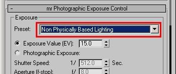
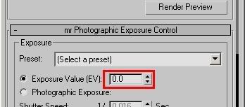
For 3ds max, the conversion factor between the total pixel value and the luminance in (cd/m^2) is the "physical scale" (found in the exposure control configuration) divided by PI.

Of course, the exposure control itself must be off or it will affect the pixel values. As a trick can be noted, that if you add an exposure control (but keep it disabled!) and set the physical scale to PI (3.1415) and render to a floating point frame buffer, the total pixel values reported when you right click on them (by the "Mono:" heading) are in cd/m^2.

/Z

2007-02-21

mental ray Wiki


The folks over at mymentalray.com has launched a mental ray Wiki.

It's almost completely empty at the moment, but together we could load it up with a lot of mental ray info!

/Z

2007-02-19

Max 9: Converting other materials to "Arch & Design"

If you want to have some cool tools for handling the Arch & Design material in Max 9 (including converting other materials - including vRay materials - into Arch & Design) you can use this script.

Save the file to your 3dsmax/scripts folder, and run it from the "MaxScript" menu.

Then go into the "Customize" menu and choose "Customize User Interface".

Go to "Menus", and on the left side open up the "mental ray" category.

On the right side, open up, say, the "Tools" menu (or any other of your choice).

Drag-and-Drop the "mr Arch Design Tools" to some cool place on that menu.

Voila - you have installed this nifty little add-on.

Note: A much simpler version of this script exists on the max 9 DVD in the sample scripts folder, but this variant is updated.

Enjoy! ;)

/Z

2007-02-17

Clouds with mental ray sky

I keep getting requests from people saying things like "I saw you at SigGraph showing of the mental ray sky and it had clouds in it. How did you do that?".


To which I twirl my moustache and say, 'tis a deep secret....

....just kidding.

Here's the thing. The mia_physicalsky shader uses a 'haze' value to derive a sky color based on the sun position/angle. So a 'hazier' sky is more white/yellowish and a less 'hazy' sky is deeper blue. Okay fine, weather control, you say, but that's not clouds, is it?

Well... actually... it is... if you modulate the haze value across the sky!

Observe this video that I made... it's basically a collection of all test animations done during the development of the sun&sky. Some are bad, some are worse, some are nice, some has bugs in them, some use very low anti aliasing, and none is a peice of art. However they do demonstrate the cloud feature...

What I did was use this texture map (which is a slightly modified version of one I found from some old CD-ROM with public domain sky textures) as a spherical environment map plugged into the haze parameter of mia_physicalsky. That's basically it!

In Maya or XSI you can do this directly, in Max you need to drag&drop your "mr Physical Sky" from your environment dialog into the material editor, uncheck the "Inherit from Sky" and apply the map there.

What is important - though - is this; This is a normal run-of-the-mill LDRI .jpg image, which means it causes a "variation" in the range 0.0-1.0 ... this is way too little for being visible as "clouds" in the sky (the haze has a range of 0 to 15)

So to see results, you need to multiply the level of the texture. How you do this differs between the applications (in Maya you can use the Gain, in Max you use the Output rollout and turn up the RGB Level, etc etc) but setting it somewhere between 5 and 10 tends to look nifty.

Note that this is not a "physically correct" effect in any way, notably because it doesn't actually scatter light, or block light, or create any shadows, or anything like that. But it does simulate "light" cloud coverage very nicely (like high altitude cirrus clouds), and the cool thing is that the clouds coloring automagically follows the sun angle, making very nice sunsets possible....


/Z

2007-02-05

Gnomon Workshop Skin Shader Tutorial

I just saw that the this very cool tutorial about my mental ray skin shader (good old misss_fast_skin), which I enjoyed very much, and I wholeheartedly recommend as a good tutorial on how to use the shaders.

Alex Alvarez has made an over two hours long video tutorial in three parts which can be downloaded from the Gnomon Workshop webpage. It's very informative and teaches many cool tricks.

A couple of details about the tutorial, though, that I thought was worth nothing:


Radii stuff

The tutorial started out by "trial and error" to find the various scattering radii. While this may be "good" as a "understand what does what" thing, I really missed my "rules of thumb" from my written SSS tutorial (available here) about the various values for the scatter radii (i.e. that the subdermal should be "about an inch" and the epidermal "about a third of an inch"). The defaults that are there are actually good if your scene is in millimeters.


Color mapping stuff

Generally, colors are not mapped in the "overall" unless you "know" what you are doing. Yes - as Alex finds out, doing it may make more intuitive sense, and may appear more "predictable" if one expects the "final color" to "look" as the "texture color".

However, the whole intended workflow of the shader is actually not to do that!

Because a lot of the "red tone" of skin should actually come from the subdermal and epidermal layers and actually hardly be present in the color map at all.

I.e. when the shader is "fully" utilized, the color map shouldn't "look" like skin at all; it should look like the skin would look if you peeled it off it's fleshy underpinning (yuck!).

It is true that some highly pigmented areas such as skin "moles" or the lip colors indeed map better in the "overall"... this is because they are a layer "on top" of the rest of the skin and actually "filter" the underlying light (blocking it) and for the lips or for skin moles, mapping "overall_color" indeed makes sense.

I fully understand that this "intended" workflow is very counter-intuitive to the lay person, but skin is such a complex substance with a lot of interaction of light between flesh, blood and the actual epidermal skin layer, it can't be as simple as "map a color map to a Blinn".

Bump stuff


I reall missed any mention about that the "appearance" of the bumps is strongly defined by the "balance" between the "diffuse" and "epidermal" layers... because the bump only applies to the unscattered "diffuse" layer, and the "epidermal" layer looks very similar to the diffuse layer, but slightly scattered and without bumps - hence one of the most important "look development" tools for the skin is to balance these two. I would actually want to see more of that rather than Alex's attempt to "blur" the bumpmap, which I do not think one should do.

Fresnel

Oh, I hate to break it to Alex, but fresnel is pronounced "frenell" [freɪ 'nel] - 'tis the name of a french dude. ;)


Reflections

The fact that Alex used something other than the build in reflectivity I can understand... but I pity the choice of the standard Maya "Blinn". I wholeheartedly suggest to use the mia_material for the reflectivity layer of skin, especially utilizing the "refl_hl_only" flag for superfast "skinny" reflections - more on that in a future post here.

I also strongly suggest to have a high "edge" reflectivity at all times, and generally let the specularity levels "follow" the levels of reflections (after all, "specularity" is really only just reflections of light sources...)

Specularities

The reason the skin shader has 2 layers of specularity isn't really to support different "areas" of skin, it's actually to change the shape of the specular "lobe". The traditional "phong" model with it's "cosine-raised-to-a-power" shaped lobe isn't really very suitable for skin, but by blending a couple of such lobes you can get a combined effect that is.


But all this whiny nit-picking aside, the tutorial is a fantastic piece of work, and I'm impressed with the time Alex took to make it (it's over two hours long!). It's well worth a download for anyone into skin shading in mental ray!

Thanks Alex for making it, and I hope you take my comments in a constructive manner!

/Z

2007-01-21

Tricks and Tips for the mia_material (Arch&Design): Volume #1

Aaah, finally; my latest handywork is finally out on all major platforms!

The material known in 3ds max as "Arch & Design" is actually a shader from the architectural.dll library known internally as the "mia_material". ("mia" is a prefix for "mental images architectural"). It is now available in XSI 6 and Maya 8.5, known as "ArchitecturalMaterial" and "mia_material" respectively.

Photobucket - Video and Image Hosting

I had to wait writing tips about this material until now, because the shader hasn't been available to everyone (at least not "officially" ;) ), but now all that is history.

So what is this thing already?

As noted by the documentation, the shader is primarily "intended" for "product design" and "architectural" renderings. By this I mean that it, basically, tries to mimic "reality" of hard surfaced... well... stuff. Nobody is stopping anyone from using it in their next feature film... just because the DLL is called "architectural" doesn't really mean much... it's a general purpose material, no more, no less.

The shader has some cool features, and some "quirks" that can be worth knowing. This post is the first in a series of Tricks&Tips which may be useful when using it.


For example, the feature to disable reflections on the "inside" of objects was intentionally intended as a performance optimization to "quickly" render glass. I'm sort of kicking myself for defaulting that to "on", because:
- it doesn't actually help performance that much
- it causes some side-effects that may be... surprising.

I simply suggest... turn it off. The importance driven ray rejection takes pretty well care of removing truly "unimportant" rays anyway, so the feature is somewhat redundant. Secondly, while it's intent is to remove the "inside" reflections, it actually kills reflection on any flipped face (because, well, the side being hit is.. uh... the "inside"!). So if you have a scene imported from a troublesome CAD system (those LOVE flipping random triangles for no reason whatsoever... it's like it's a secret evil plot... oh no... you're only gonna get 75% of your triangles flipped correctly... ha ha... ) you could suddenly get NO reflections on some of them, which looks really weird... without any "transparency" being involved anywhere! Why? Because the "wrong" triangles are showing their "inside"... and hence.... no reflections... as per the option!

Thousand apologies for this "misfeature" ;)

More to follow, but let me drop a hint; Have you tried combining the SSS shaders with the mia_material's reflection feature?

Also, check out the refl_hl_only flag, and do read the docs there.... it's NOT simply a "highlights only" flag. If you use FG, it's a "super-quick fast fake for the ultra-mega-blurry reflections". Like those of... say... skin.

Stay tuned.


/Z