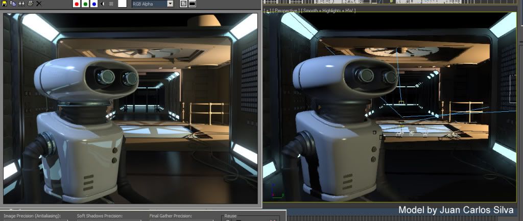
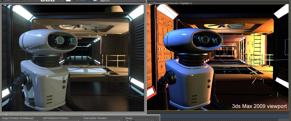
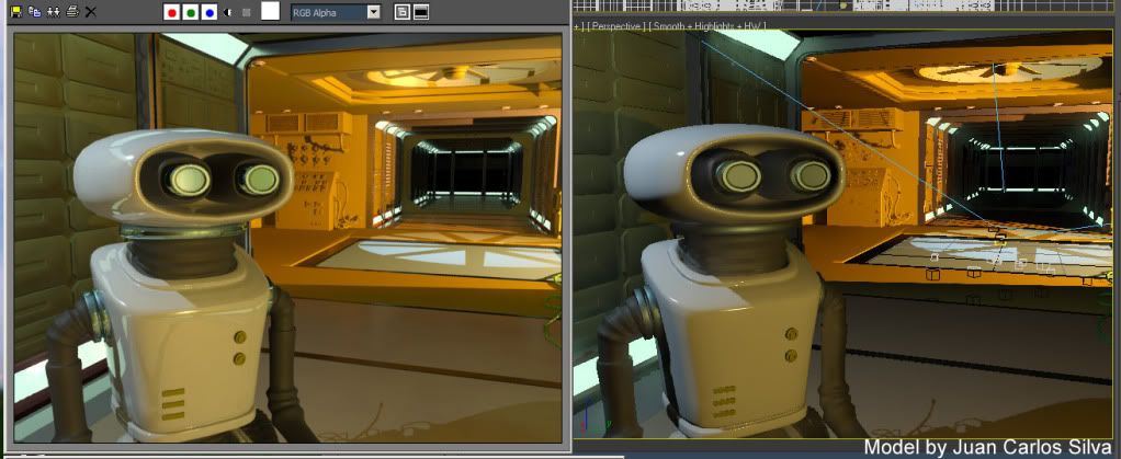
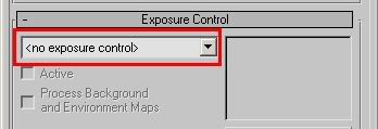
The most common "complaints" I get about mental ray rendering in 3ds Max 2008 is "it's washed out" and "it Renders black". The answer to the former is "you are not handling your gamma correctly", and will be thorougly covered in the future. The answer to the latter is "You are not understanding the Physical Scale" settings. Which is what we're going to talk about now.
Color and Color
Without going too deep into the physics of photometric units (
we did that already) we must understand that a normal color, an RGB value, i.e. a pixel color of some sort, can, fundamentally represent one of two different things:
- A reflectance value
- A luminance (radiance) measurement
The "luminance" of something is simply how bright it looks. It's probably the most intuitively understandable lighting unit. Basically, you can say that when you are looking at the pixels your digital camera spit out on your computer, you are looking at pixels as individual luminance measurements, converted back to luminance variations by your screen.
I.e. a given luminance of some real world object flows in through the lens of your camera, hits the imaging surface (generally a CCD of some kind) and gets converted to some value. This value (for the moment ignoring things like transfer curves, gamma, spectral responses and whatnot) is, in principle, proportional to the luminance of the pixel.
Now "reflectance" is how much something reflects. It is often
also treated in computer graphics as a "color". Your "diffuse color" is really a "diffuse reflectance". It's not really a pixel value (i.e. a "luminance") until you throw some light at it to reflect.
And herein lies the problem; traditionally, computer graphics has been very lax with treating luminance and reflectance as interchangeable properties, and it's gotten away with this because it has ignored "exposure", and instead played with light intensity. You can tell you are working with "oldschool" rendering if your lights is of intensities like "1.0" or "0.2" or something like that, in some vague, unit-less property.
So when working "oldschool" style, if you took an image (some photo of a house, for example) and applied as a "background", this image was just piped through as is, black was black, white was white, and the pixels came through as before. Piece of cake.
Also, if you took a light of intensity "1.0" that shone perpendicular on a diffuse texture map (some photo of wood, I gather) will yield exactly those pixels back in the final render.
Basically, the wood "photo" was treated as "reflectance", which was then lit with something arbitrary ("1.0") and treated on screen as luminance. The house photo, however, was treated as luminance values directly.
But here's the problem: Reflectance is inherently limited in range from 0.0 to 1.0... i.e. a surface can never reflect more than 100% of the light it receives (ignoring fluorescence, bioluminescence, or other self-emissive properties), whereas actual real-world
luminance knows no such bounds.
Now consider a photograph... a real, hardcopy, printed photograph. It actually reflects the light you shine on it. You can't watch a photograph in the dark. So what a camera does is to take values that are luminances, take it through some form of
exposure (using different electronic gains, chemical responses, irises to block light, and modulating the amount of time the imaging surfaces is subjected to the available luminances). Basically, what the camera does, is to take a large range (0-to-infinity, pretty much) and convert it down to a low rang (0-to-1, pretty much).
When this is printed as a hardcopy, it indeed is basically converting luminances, via exposure, into a reflectance (of the hardcopy paper). But this is just a representation. How bright (actual luminance) the "white" part of the photographic hardcopy will be depends on how much light you shine on the photograph when you view it - just like how bright (actual lumiance) the "white" part of the softcopy viewed on the computer depends on the brighness knob of the monitor, the monitors available emissive power, etc.
The funny thing with the human visual system is that it is really adaptive, and can view this image and fully understand and decode the picture even though the absolute luminance of the "white" part of the image varies like that. Our eyes are really adaptive things. Spiffy, cool things.
So, the flow of data is:
- Actual luminance in the scene (world)
- going through lens/film/imaging surface and is "exposed" (by the various camera attributes) and
- becomes a low dynamic range representation on the screen, going from 0-to-1 (i.e. from 0% to 100% at whatever max brightness the monitor may have for the day).
So, now the problem.
In the oldschool world we could draw a near equivalence between the "reflectance" interpretation and the "luminance" interpretation of a color. Our "photo of wood" texture looked the same as "photo of house" background.
What if we use a physical interpretation?
What about our "photo of wood"? Well, if we ignore the detail of the absolute reflectance not necessarily being correct due to us not knowing the exposure or lighting whtn the "photo of wood" being taken, it is still a rather useful way to reperesent wood reflectance.
So, if we shine some 1000's of lux of light onto a completely white surface, and expose the camera such that this turns into a perfectly white (without over-exposure) pixel on the screen, then applying this "photo of wood" as a texture map will yeild
exactly the same result as the "oldschool" method. Basically, our camera exposure simply counter-acted the absolute luminance introduced by the light intensity.
So, in short, the "photo of wood" used interpreted as "reflectance" still works fine (well, no less "fine" than before).
What about us placing our "photo of house" as the background?
Well,
now things start to change... we threw some thousands of lux onto the photo, creating a luminance likely in the thousands as well.... these values "in the thousands" was then converted to a range from black-to-white by the
exposure.
So what happens with our "photo of house"? Nothing has told it to be anything than a 0-to-1 range thing. Basically, if interpreted strictly as luminance values, the exposure we are using (the one converting something in the thousands to white) will covert something in the range of 0-1 to.... pitch black. It won't even be enough to wiggle the lowest bit on your graphics card.
You will see nothing. Nada.
Zip. BLACKNESS!So, assuming you interpret oldschool "0-to-1" values directly as luminance, you will (for most common exposures)
not see anything.
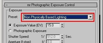
Now
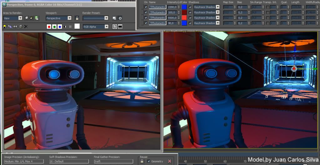
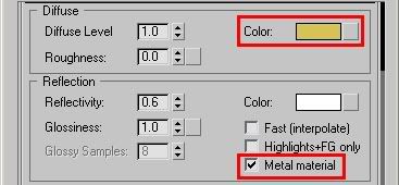
this is the default behaviour of the mr Photographic Exposure control!!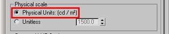
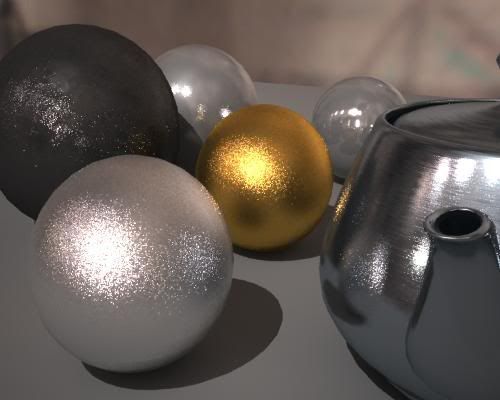
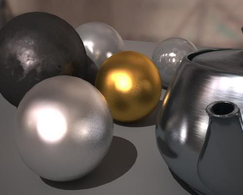
This setting (pictured above) from the
mr Photographic Exposure will interpret any "oldschool" value directly as a cd/m^2 measurement. And will, with most useful exposures used for most scenes, result in the value "1" representing anything from complete blackness to near-imperceptible-near-blackness.
(I admit, I've considered many a time that making this mode
the default was perhaps not the best choice)
So how do we fix it
Simple. There are two routes to take:
- Simply "know what you are doing" and take into account that you need to apply the "luminance" interpretation at certain points, and scale the values accordingly.
- Play with the "Physical Scale" setting
Both of these methods equate to roughly the same result, but the former is a bit more "controlled". I.e. for a "background photo" you will need to boost it's intensity to be in the range of the "thousands" that may be necessary to show up for your current exposure. In the
Output rollout, turn up "RGB Level" very high.
Of course, in an ideal world you would have your background photo taken at a known exposure, or where you had measured the luminance of some known surface in the photo, and you would set the scaling accordingly. Or even better, your background image is already a HDR image calibrated directly in cd/m^2.
But what of the other method?
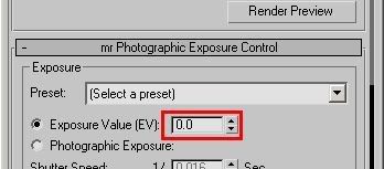
Undersanding the 'Physical Scale' in 3ds Max
When you are using the
mr Phogographic Exposure control, and you switch to the "Unitless" mode...
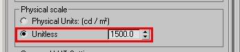
...one can say that this parameter now is a "scale factor" between any "oldschool" value and physical values. So you can
think of it as if any non-photometric value (say, pixel values of a background image, or light intensities of non-photometric lights) were roughly multiplied by this value before being interpreted as physical values.
(This, however, is a simplification; under the hood it actually does the opposite, it is the physical values that are scaled in relation to the "oldschool" values, but since the exposure control exactly "undoes" this in the opposite direction, the apparent practical result of this is that it seems to "scale" any oldschool-0-1 values)When to use which mode
Which method to use is up to you. You may need to know a few things, though: The "cd/m^2" mode is a bit more controllable and exact. However, the "Unitless" mode is
how the other Exposure controls, such as the Logarithmic, work by default. Hence, for a scene created with a logarithmic exposure, to get the same lighting balance between photometric things and "oldschool" things, you
must use the unitless mode.
Furthermore, certain features of 3DS Max actually works incorrectly, indeed limiting their output to a "0-1" range. Notable here is many of the volumetric effects like fog. Hence, if the "cd/m^2 mode" is used, it blocks fog intensity to max out at "1 cd/m^2". This causes things like fog or volume light cones to appear black! That is bad.
Whereas in the "Unitless" mode, the value of "Physical Scale" basically defines how bright the "1.0" color "appears", and this gets around any limitation of the (unfortunately) clamping volume shaders.
BTW: I actually
already covered this topic in an earlier post, but it seems that I needed to go into a bit more detail, since the question still arise quite often on various fora.
Hope this helps...
/Z